Don’ts for Flex Circuits
The materials used in flex circuits dissipate heat better than rigid PCBs, and this helps to keep the circuit cool. They also resist chemicals, radiation and UV exposure that might otherwise damage a traditional PCB. These characteristics enable flex circuits to be placed in products that need to be exposed to harsh environmental conditions without affecting the performance of the product.
However, a flex circuit is not a replacement for a traditional rigid circuit board in all situations. It’s important to understand the limitations of flex circuits when designing your next project. To help you, we’ve put together a list of Dos and Don’ts to consider for your next flex circuit project.
The layer stack of a flex circuit is quite different than a rigid PCB. There are multiple copper foil layers which need to be etched. These layers can be of different thicknesses and types, but they need to match the thickness of the underlying polyimide. This is because the layer stack determines a lot of the physical and electrical properties of a flex circuit.
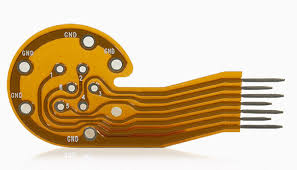
Dos and Don’ts for Flex Circuits
In addition to the layer stack, you should also consider the bend radius of your flex circuit. The tighter the bend radius, the less likely your circuit will be to fail during flexing. You can minimize the effect of this by routing your conductors in a way that limits the amount of flexing they must undergo. For example, routing the signal layers with a tangential curved corner rather than a straight one is helpful.
The copper foil used in a flex circuit is normally a thin film of either wrought or electrodeposited metal. While there are a number of other metals that can be used, copper is a good choice for most applications as it offers a balanced combination of cost and physical and electrical performance. The metallization of a flex circuit can be done in several ways, but the most common is to use pad fillets to improve etch yield and copper thickness distribution. In addition to improving etch yield and thickness, pad fillets can also be used to reduce trace signal impedance.
Other issues that need to be considered for a flex circuit include the use of adhesives and avoiding excessive bending. When using an adhesive on a flex circuit, it’s important to make sure the adhesive is a pressure-sensitive type (PSA) that will adhere well when heat and pressure are applied. It’s also important to keep in mind that flex materials have a higher Z-axis expansion than rigid materials and this can affect the adhesion of your components.
You should also be aware that flex materials can tear when they’re bent at sharp corners. This is why IPC recommends terminating flex-circuit endpoints at a connector when possible and ensuring that corners are terminated with radii greater than 1.5 mm (about 60 mils).